
16
TM 5-2410-241-23-2
FIELD MAINTENANCE
-
REAR GEAR ASSEMBLY REPLACEMENT
0085
Removal, Cleaning and Inspection, Installation
INITIAL SETUP
References
Tools and Special Tools
0
0
Tool Kit, General Mechanic's
WP 0295
0
(WP 0302, Item 65)
0
Equipment Condition
0
Wrench, Torque, Click, Ratcheting, 1/2" Drive,
Machine parked (TM 5-2410-241-10)
250 lb-ft (WP 0302, Item 71)
0
0
Implement pump removed (WP 0112)
Wrench, Torque, Click, Ratcheting, 3/8" Drive,
0
Flange removed (WP 0104)
75 lb-ft (WP 0302, Item 73)
0
0
Flywheel removed (WP 0100)
0
Materials/Parts
0
Drawing Required
Rag, Wiping (WP 0303, Item 24)
0
0
Bearings (4)
TM 5-2410-241-24P, Figure 38, 43
0
0
O-ring (4)
0
Estimated Time to Complete
0
6.0 Hr
0
REMOVAL
00085
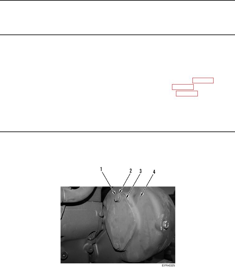
1. Remove two bolts (Figure 1, Item 1), washers (Figure 1, Item 2) and cover (Figure 1, Item 3) from flywheel
housing (Figure 1, Item 4).
Figure 1. Cover and Retaining Hardware on Left Side of Flywheel Housing.
0085