
TM 5-2410-241-23-2
0085
REMOVAL CONTINUED
N OT E
Note orientation of hydraulic pump adapter and gear.
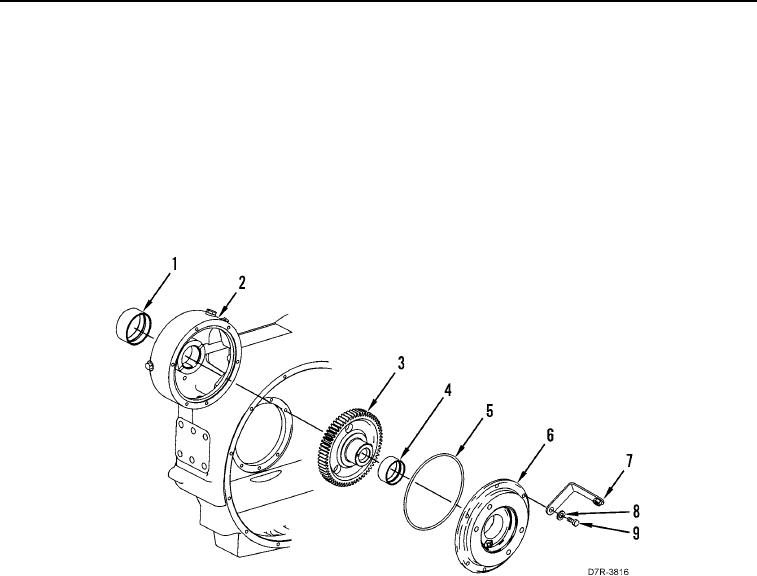
8. Remove six bolts (Figure 6, Item 9), washers (Figure 6, Item 8), bracket (Figure 6, Item 7), hydraulic pump
adapter (Figure 6, Item 6), O-ring (Figure 6, Item 5), and pump drive gear (Figure 6, Item 3) from flywheel
housing (Figure 6, Item 2). Discard O-ring.
9. Remove bearing (Figure 6, Item 4) from hydraulic pump adapter (Figure 6, Item 6). Discard bearing.
10. Remove bearing (Figure 6, Item 1) from flywheel housing (Figure 6, Item 2). Discard bearing.
Figure 6. Left Pump Drive Gear.
0085