
TM 5-2410-241-23-2
0105
REMOVAL CONTINUED
N OT E
Note harness routing to aid installation.
Tag and mark all electrical connections to aid installation.
Note location of tiedown sraps to aid installation.
t
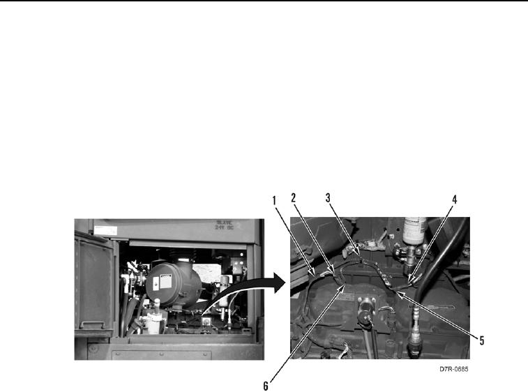
8. Remove tiedown straps (Figure 4, Item 3) from harness (Figure 4, Item 1). Discard tiedown straps.
9. Disconnect ether aid connector (Figure 4, Item 4) from connector (Figure 4, Item 5).
10. Disconnect connector (Figure 4, Item 2) from air inlet manifold pressure connector (Figure 4, Item 6). Position
harness (Figure 4, Item 1) aside.
Figure 4. Fuel Temperature Harness.
00105