• Home
  • Download PDF
  • Order CD-ROM
  • Order in Print
Figure 13. Coolant Sensor Harness.
Figure 15. Crankshaft Sensor Harness.

Field Maintenance Manual D7R Dozer Type I With Winch and Type II With Ripper
Page Navigation
  444    445    446    447    448  449  450    451    452    453    454  
img
.
TM 5-2410-241-23-2
0105
INSTALLATION CONTINUED
N OT E
Install electrical connections, harness routing and tiedown straps as noted during removal.
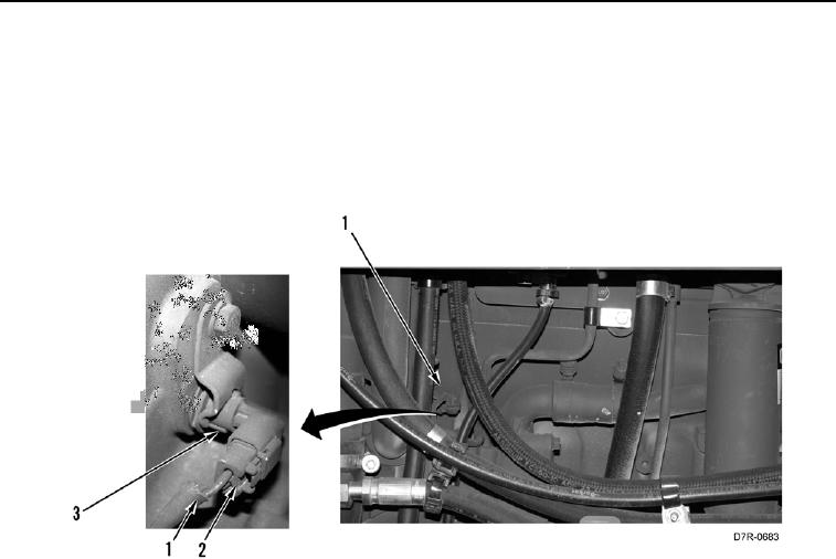
15. Connect connector (Figure 14, Item 2) on camshaft speed sensor (Figure 14, Item 3).
16. Install new tiedown straps on harness (Figure 14, Item 1).
Figure 14. Camshaft Sensor Harness.
00105
0105-14


Privacy Statement
Press Release
Contact

© Copyright Integrated Publishing, Inc.. All Rights Reserved.