
TM 5-2410-241-23-2
0139
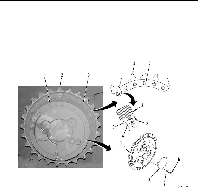
INSTALLATION CONTINUED
16. Install two washers (Figure 12, Item 4), bolts (Figure 12, Item 5), and nuts (Figure 12, Item 3) on sprocket
segment (Figure 12, Item 2).
17. Tighten nuts (Figure 12, Item 3) to 221 lb-ft (300 Nm).
18. Tighten nuts (Figure 12, Item 3) an additional 1/3 turn.
19. Check torque on nuts (Figure 12, Item 3). Minimum torque on nuts to 420 lb-ft (570 Nm).
20. Remove three bolts (Figure 12, Item 6), washers (Figure 12, Item 7), and cap (Figure 12, Item 8) from final
drive assembly (Figure 12, Item 1).
Figure 12. Cap and Sprocket Bolts.
0139
END OF TASK