
TM 5-2410-241-23-2
0140
REMOVAL CONTINUED
6. Position hydrostatic drive motor (Figure 4, Item 5) on flat level surface.
7. Remove lifting device and forcing screw from hydrostatic drive motor (Figure 4, Item 5).
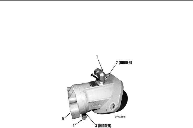
8. Remove fitting (Figure 4, Item 1) from hydrostatic drive motor (Figure 4, Item 5).
9. Remove two O-rings (Figure 4, Item 2) from fitting (Figure 4, Item 1). Discard O-rings.
10. Remove fitting (Figure 4, Item 4) from hydrostatic drive motor (Figure 4, Item 5).
11. Remove two O-rings (Figure 4, Item 3) from fitting (Figure 4, Item 4). Discard O-rings.
Figure 4. Fittings.
0140
CLEANING AND INSPECTION
000140
Clean and inspect all parts IAW Mechanical General Maintenance Instructions (WP 0295).
END OF TASK