
TM 5-2410-241-23-2
0145
REMOVAL CONTINUED
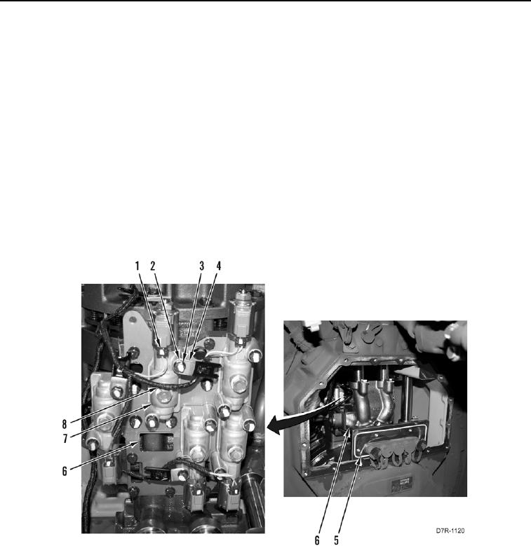
4. Remove O-ring (Figure 2, Item 5) from manifold. Discard O-ring.
N OT E
Note harness routing to aid installation.
Tag and mark all electrical connections to aid installation.
5. Disconnect connector (Figure 2, Item 1) from transmission clutch solenoid (Figure 2, Item 7).
N OT E
Note location and position of harness clips. Not all solenoids will have a harness and
harness clips to position aside.
6. Remove two bolts (Figure 2, Item 3), washers (Figure 2, Item 2), and one harness clip (Figure 2, Item 4) from
transmission clutch solenoid (Figure 2, Item 7). Position harness (Figure 2, Item 8) and harness clip aside.
7. Remove transmission clutch solenoid (Figure 2, Item 7) from transmission control valve (Figure 2, Item 6).
Figure 2. Transmission Solenoid.
0145
END OF TASK
CLEANING AND INSPECTION
000145
Clean and inspect all parts IAW Mechanical General Maintenance Instructions (WP 0295).
END OF TASK