
TM 5-2410-241-23-2
0145
INSTALLATION
000145
N OT E
The following procedure will remove one transmission clutch solenoid. Follow same
procedure to remove additional transmission clutch solenoids.
1. Position transmission clutch solenoid (Figure 2, Item 7) on transmission control valve (Figure 2, Item 6).
N OT E
Note location and position of harness clips. Not all solenoids will have a harness and
harness clips to position aside.
2. Position harness (Figure 2, Item 8) and install one harness clip (Figure 2, Item 4), two washers (Figure 2,
Item 2), and bolts (Figure 2, Item 3) on transmission clutch solenoid (Figure 2, Item 7).
N OT E
Install electrical connections and harness routing as noted during removal.
3. Connect connector (Figure 2, Item 1) on transmission clutch solenoid (Figure 2, Item 7).
4. Install new O-ring (Figure 2, Item 5) on manifold.
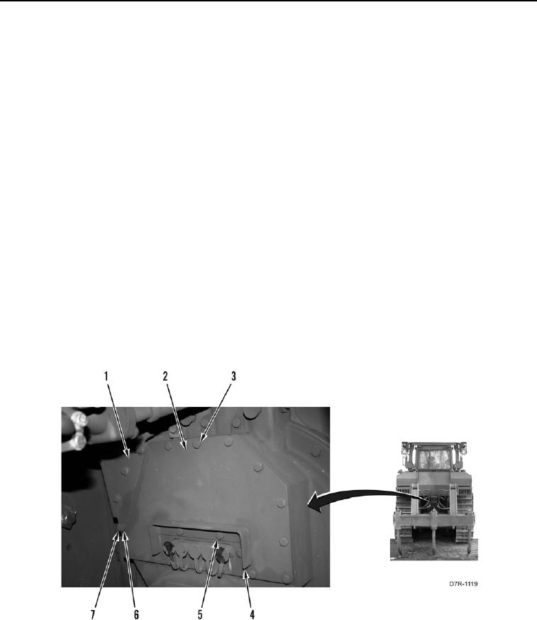
5. Install plate (Figure 3, Item 2) and 15 bolts (Figure 3, Item 3) on machine.
6. Install guard (Figure 3, Item 4) and two bolts (Figure 3, Item 5) on machine.
7. Install guard (Figure 3, Item 1), four washers (Figure 3, Item 6), and bolts (Figure 3, Item 7) on machine.
Figure 3. Plate.
0145
END OF TASK