
TM 5-2410-241-23-2
0157
FUEL SUPPLY AND RETURN LINE REMOVAL CONTINUED
N OT E
Note position of retaining straps and routing of hoses to aid installation.
18. Remove fuel tank (WP 0171).
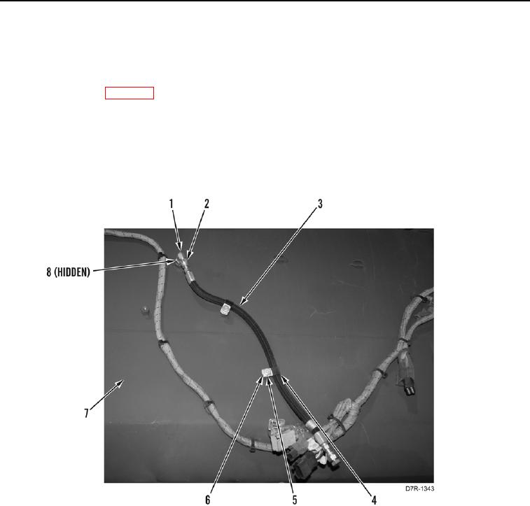
19. Remove two bolts (Figure 7, Item 5), washers (Figure 7, Item 6), and P clips (Figure 7, Item 4) from hose
(Figure 7, Item 3).
20. Loosen tube nut (Figure 7, Item 2) and remove hose (Figure 7, Item 3) from elbow (Figure 7, Item 1).
21. Remove elbow (Figure 7, Item 1) and two O-rings (Figure 7, Item 8) from tank (Figure 7, Item 7). Discard
O-rings.
Figure 7. Tank Return Line.
0157
END OF TASK