
TM 5-2410-241-23-2
0157
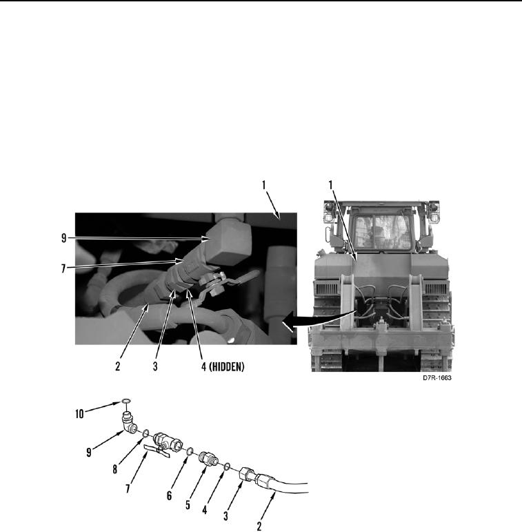
FUEL SUPPLY AND RETURN LINE REMOVAL CONTINUED
N OT E
Note position and orientation of fittings to aid in installation.
7. Loosen tube nut (Figure 3, Item 3) and remove hose (Figure 3, Item 2) and O-ring (Figure 3, Item 4) from fitting
(Figure 3, Item 5). Discard O-ring.
8. Remove fitting (Figure 3, Item 5) and O-ring (Figure 3, Item 6) from valve (Figure 3, Item 7). Discard O-ring.
9. Remove valve (Figure 3, Item 7) and O-ring (Figure 3, Item 8) from fitting (Figure 3, Item 9). Discard O-ring.
10. Remove fitting (Figure 3, Item 9) and O-ring (Figure 3, Item 10) from tank (Figure 3, Item 1). Discard O-ring.
Figure 3. Tank Supply Line.
0157