
TM 5-2410-241-23-3
0197
REMOVAL CONTINUED
N OT E
It may be necessary to remove or loosenother hoses to gain access to bolts.
Note position and orientation of each hose to aid installation.
Hoses will be removed fom engine compartment.
r
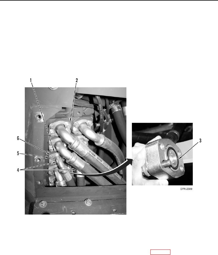
22. Remove eight bolts (Figure 11, Item 5), washers (Figure 11, Item 6), and two flanges (Figure 11, Item 1) from
two hoses (Figure 11, Item 4).
23. Disconnect two hoses (Figure 11, Item 4) from control valve (Figure 11, Item 2), and remove and discard two
O-rings (Figure 11, Item 3).
Figure 11. Implement Valve.
0197
END OF TASK
CLEANING AND INSPECTION
000197
Clean and inspect all parts IAW Mechanical General Maintenance Instructions (WP 0295).
END OF TASK