
TM 5-2410-241-23-3
0203
DOOR ROD ASSEMBLY
000203
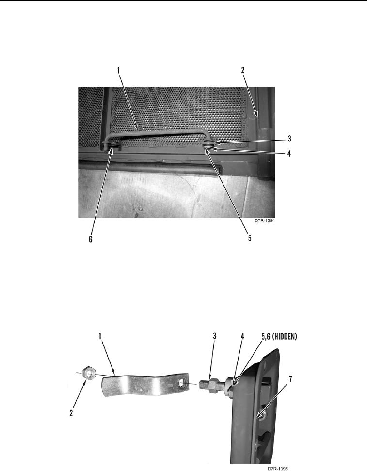
1. Install grommet (Figure 8, Item 6) on door assembly (Figure 8, Item 2).
2. Install grommet (Figure 8, Item 3) on rod (Figure 8, Item 1).
3. Install rod (Figure 8, Item 1), washer (Figure 8, Item 4), and new cotter pin (Figure 8, Item 5) on door assembly
(Figure 8, Item 2).
Figure 8. Door Rod.
0203
END OF TASK
DOOR LATCH ASSEMBLY
000203
1. Install latch handle (Figure 9, Item 3), two washers (Figure 9, Item 5), bolts (Figure 9, Item 6), and new
locknuts (Figure 9, Item 4) on latch assembly (Figure 9, Item 7).
2. Install pawl (Figure 9, Item 1) and new locknut (Figure 9, Item 2) on latch (Figure 9, Item 3).
Figure 9. Latch Pawl.
0203