
TM 5-2410-241-23-3
0268
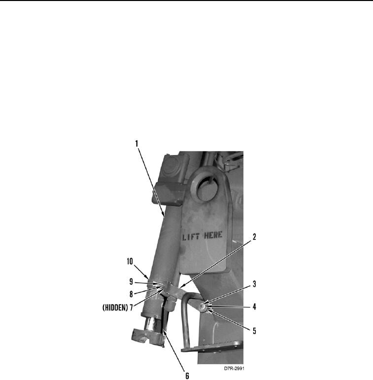
REMOVAL. CONTINUED
6. Install retaining clamps on lift cylinders (Figure 4, Item 1).
a. Collapse lift cylinder (Figure 4, Item 1) (TM 5-2410-241-10).
b. Install two heavy duty tiedown straps (Figure 4, Item 6) to hold lift cylinder in collapsed position.
Install bar (Figure 4, Item 2), spacer (Figure 4, Item 5), washer (Figure 4, Item 4), and bolt (Figure 4,
c.
Item 3) loosely on machine.
d. Install two half-clamps (Figure 4, Item 10), bar (Figure 4, Item 2), bolt (Figure 4, Item 9), two washers
(Figure 4, Item 7), and nut (Figure 4, Item 8) on lift cylinder (Figure 4, Item 1).
e. Tighten all nuts and bolts.
Repeat substeps a-e for other lift cylinder (Figure 4, Item 1).
f.
Figure 4. Retaining Clamps.
0268