
TM 5-2410-241-23-3
0272
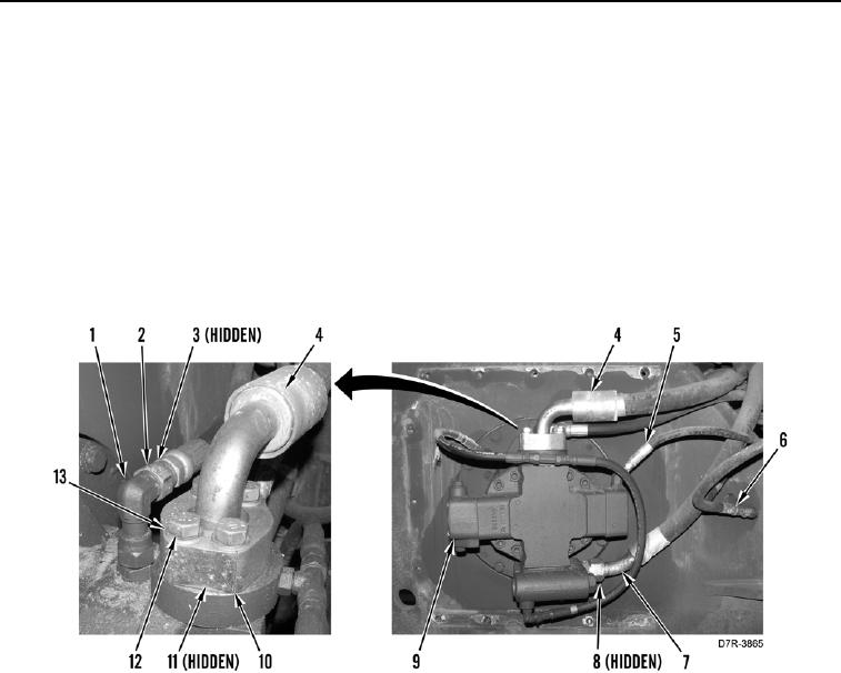
INSTALLATION CONTINUED
N OT E
Connect hoses as marked during removal.
11. Install new O-ring (Figure 11, Item 8) and connect hose (Figure 11, Item 7) on winch motor (Figure 11, Item 9).
12. Install new O-ring (Figure 11, Item 11) on hose (Figure 11, Item 4).
13. Connect hose (Figure 11, Item 4) on winch motor (Figure 11, Item 9) and install flanges (Figure 11, Item 10),
four washers (Figure 11, Item 13), and bolts (Figure 11, Item 12).
14. Install three new O-rings (Figure 11, Item 3) and hoses (Figure 11, Items 2, 5, and 6) on fittings (Figure 11,
Item 1).
Figure 11. Winch Hoses.
0272