
TM 5-2410-240-23-1
0007
HYDRAULIC SYSTEMS CONTINUED
Right Side Hydrostatic Pump Charge Pump Operation
0007
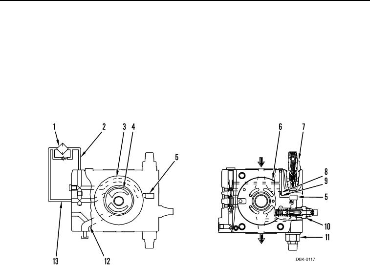
As the wear plate (Figure 6, Item 4) rotates, oil is drawn through the supply passage (Figure 6, Item 12) and is then
forced out through the passage (Figure 6, Item 13). Oil then flows through the hydraulic oil filter (Figure 6, Item 1)
and returns through the passage (Figure 6, Item 2). Oil then flows through the passage (Figure 6, Item 3), then
through the supply passage (Figure 6, Item 5), then through passage (Figure 6, Item 9), and out through the orifice
(Figure 6, Item 8). The oil then flows through the passage (Figure 6, Item 6) to the piston pump's control valve. Oil
also flows from the supply passage to the crossover relief valve (Figure 6, Item 7), the charge relief valve (Figure 6,
Item 10), and the crossover relief valve (Figure 6, Item 11).
Figure 6. Right Side Hydrostatic Pump Charge Pump.
0007