
TM 5-2410-240-23-1
0007
HYDRAULIC SYSTEMS CONTINUED
Crossover Relief Valve Description
0007
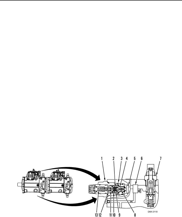
The crossover relief valve (Figure 7, Item 1) performs multiple functions within the piston pump. First, the
crossover relief valve operates as a makeup valve to provide makeup oil to the drive loop for any oil leakage within
the system. It also provides makeup oil for oil flow through the piston motor flushing valve. Second, the crossover
relief valve operates as a high-pressure relief to limit spikes or shocks to a drive loop.
The crossover relief valve should open only to handle pressure spikes. The spring setting is above the rated
pressure specification for stalls. Spikes usually occur from external forces. This may include bumping the machine
into a tree or similar object.
Makeup Valve Operation
0007
When the oil pressure in the spring chamber (Figure 7, Item 9) and the force of the spring (Figure 7, Item 2) is less
than the charge oil pressure in the passage (Figure 7, Item 3), charge oil pressure forces the valve spool (Figure 7,
Item 4) to move to the left. Charge oil then flows from the passage (Figure 7, Item 6) through the passage past the
spool through the passage (Figure 7, Item 5), and back to the drive loop.
Relief Valve Operation
0007
Oil flows from the drive loop to the crossover relief valve (Figure 7, Item 1) through the passage (Figure 7, Item 2).
Oil flows through the passage (Figure 7, Item 8) into the spring chamber (Figure 7, Item 9). Oil pressure combines
with the spring in the spring chamber to hold the valve (Figure 7, Item 4) closed. The oil also acts against the pilot
valve (Figure 7, Item 11), which the spring (Figure 7, Item 13) holds closed.
If the oil pressure in the spring chamber (Figure 7, Item 9) increases enough to overcome the force of the spring
(Figure 7, Item 13), the oil pressure causes the pilot valve (Figure 7, Item 11) to move to the left. When the pilot
valve moves to the left, the valve opens a path for the oil in the spring chamber to flow from the pilot valve through
to the passage (Figure 7, Item 10) to the outlet port of the port (Figure 7, Item 12) to the crossover relief valve
(Figure 7, Item 1).
Since the pilot valve (Figure 7, Item 11) is open to the low-pressure pilot oil circuit, hydraulic oil that is acting
against the valve (Figure 7, Item 4) can now overcome the force of the spring (Figure 7, Item 2) in the spring
chamber (Figure 7, Item 9). The oil pressure against the valve forces the valve to the left and the valve opens.
Because the valve is open, the oil flows through the pilot oil circuit. The oil then flows through the charge relief
valve (Figure 7, Item 7) to the case drain.
Figure 7. Crossover Relief Valve.
0007