
TM 5-2410-240-23-1
0007
HYDRAULIC SYSTEMS CONTINUED
Hydrostatic Drive Motor (Displacement) Control Valve
0007
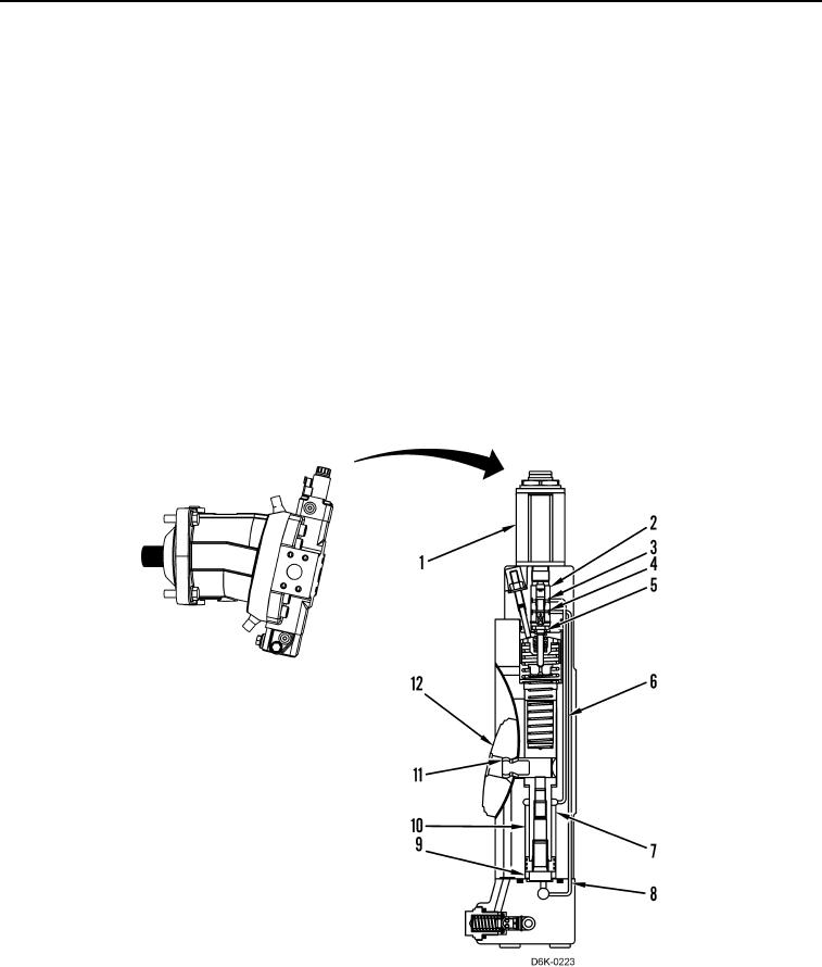
High-pressure oil from the drive loop flows into the cavity (Figure 12, Item 7), which forces the shift actuator piston
(Figure 12, Item 10) downward. The high-pressure oil also flows through the passage (Figure 12, Item 6) and the
passage (Figure 12, Item 3) to the valve (Figure 12, Item 2). In addition, the oil in the cavity (Figure 12, Item 9)
flows through the passage (Figure 12, Item 8) and the passage (Figure 12, Item 4) to the valve.
When there is no signal from the machine ECM to the solenoid (Figure 12, Item 1), the valve (Figure 12, Item 2)
does not move and the pressure oil in the passage (Figure 12, Item 3) is blocked. In addition, the oil in the passage
(Figure 12, Item 4) flows past the valve in the motor case.
When the machine ECM sends a signal to the solenoid (Figure 12, Item 1), the solenoid overcomes the force of the
spring (Figure 12, Item 5) and the valve (Figure 12, Item 2) moves downward. As the valve moves downward, a
path between the passage (Figure 12, Item 3) and the passage (Figure 12, Item 4) opens. Regulated pressure oil
flows from the passage past the valve into the passage and then through the passage (Figure 12, Item 8) into the
cavity (Figure 12, Item 9).
Since the surface area of the shift actuator piston (Figure 12, Item 10) in the cavity (Figure 12, Item 9) is greater
than the surface area of the shift actuator piston in the cavity (Figure 12, Item 7), the shift actuator piston moves
upward. Since the pin (Figure 12, Item 11) connects to the shift actuator piston, the pin also moves upward moving
the control lens (Figure 12, Item 12) to the desired angle.
Figure 12. Hydrostatic Drive Motor (Displacement) Control Valve.
0007