TM 5-2410-240-23-1
0007
HYDRAULIC SYSTEMS CONTINUED
Flushing Valve
0007
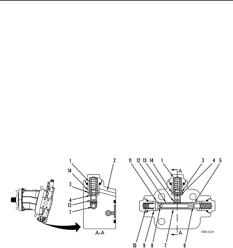
When the steering and transmission control is in the NEUTRAL position, both sides of the drive loop have equal
pressure. Oil flows from one side of the drive loop through the port (Figure 13, Item 8) into the chamber (Figure 13,
Item 11). Oil also flows from the other side of the drive loop through the port (Figure 13, Item 6) into the chamber
(Figure 13, Item 5). Since the oil pressure on both sides of the drive loop is equal, the oil pressure in the chamber
(Figure 13, Item 11) and in the chamber (Figure 13, Item 5) is equal. As a result, the spool (Figure 13, Item 7) is
centered, and oil does not flow through the rest of the flushing valve.
When the steering and transmission control is moved to the FORWARD or REVERSE position, one side of the
drive loop has a greater pressure than the other side. High-pressure oil from one side of the drive loop flows
through the port (Figure 13, Item 6) into the chamber (Figure 13, Item 5) and reduced pressure oil from the other
side of the drive loop flows through the port (Figure 13, Item 8) into the chamber (Figure 13, Item 11). Since the oil
pressure in the chamber (Figure 13, Item 5) is greater than the oil pressure in the chamber (Figure 13, Item 11), the
spool (Figure 13, Item 7) shifts to the left until it contacts the spacer (Figure 13, Item 9). The oil pressure in the
chamber (Figure 13, Item 5) overcomes the force of the spring (Figure 13, Item 10) and the spool (Figure 13,
Item 7) and the spacer continue to move to full travel.
As the spool (Figure 13, Item 7) moves to full travel, it opens the chamber (Figure 13, Item 11) to the chamber
(Figure 13, Item 12). Reduced pressure oil flows from the port into the chamber (Figure 13, Item 12) and then
through the orifice (Figure 13, Item 13). The restriction of oil flow through the orifice creates pressure for the spool
(Figure 13, Item 3) against the spring (Figure 13, Item 1). As the pressure of the spool overcomes the force of the
spring (Figure 13, Item 1), the passage (Figure 13, Item 4) opens to the chamber (Figure 13, Item 14). Then, the oil
flows from the orifice through the passage of the spool into the chamber (Figure 13, Item 14) and then through the
passage (Figure 13, Item 2) to the case of the piston motor. This oil lubricates the piston motor components.
Figure 13. Flushing Valve.
0007

