TM 5-2410-240-23-1
0007
HYDRAULIC SYSTEMS CONTINUED
Powertrain Return Manifold Description
0007
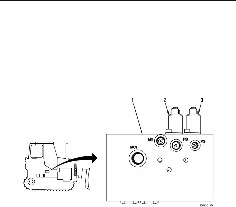
The powertrain return manifold (Figure 14, Item 1) is located beneath the cab to the left of the right side hydrostatic
pump. The manifold routes oil flow from the case drains of the pumps and motors in the powertrain system. The
return is divided into four systems. The components are the oil cooler system, the brake system, the drive system,
and the hydraulic tank.
The manifold contains an oil cooler bypass valve, a parking brake solenoid (Figure 14, Item 2), and a transmission
pilot supply (override) solenoid (Figure 14, Item 3). The oil cooler bypass valve consists of poppets and springs.
The valve maintains the hydraulic oil at the optimum operating temperature. For SAE 10W hydraulic oil, the valve
maintains an operating temperature of 140F (60C). The parking brake solenoid routes pilot oil in order to apply
the parking brakes and to disengage them. The transmission pilot supply (override) solenoid controls the
proportional solenoid valves on each hydrostatic motor. The transmission pilot supply (override) solenoid allows oil
to either route to the proportional valves or it blocks oil flow to the valves.
Figure 14. Powertrain Return Manifold.
0007
Powertrain Return Manifold Operation
0007
Oil flows from the case drains of the pumps and motors to either the oil cooler or the hydraulic tank. When the
operator starts the machine, the oil temperature is cool and the case drain pressure is high. The force moves the
springs (Figure 15, Items 15 and 13) and the poppets (Figure 15, Items 14 and 12) downward in order to open the
oil flow. The components will not be able to overcome the pressure of the cool return oil (Figure 15, Items 4 and 10)
and the oil cooler bypass valve opens. Most of the return oil flows through the port (Figure 15, Item 17) to the
hydraulic tank.
When the temperature of the oil is very high, the viscosity of the return oil is very low. The flow resistance to the
hydraulic oil cooler is also low. Thus, the pressure of the return oil from the case drain is low. As a result, the hot oil
flows through the ports (Figure 15, Items 5 and 6). The low-pressure oil will not overcome the force of the spring
(Figure 15, Items 15 and 13) and the hot oil (Figure 15, Items 7 and 8) flows through the port (Figure 15, Item 9) to
the oil cooler and returns through the port (Figure 15, Item 11) and then flows back to the tank.

