
6
TM 5-2410-240-23-1
FIELD MAINTENANCE
-
THEORY OF OPERATION UNDERCARRIAGE
0
009
UNDERCARRIAGE SYSTEM
0009
Undercarriage Components
0009
The undercarriage connects the frame of the machine to the track roller frames. It also provides support for the
machine's weight and helps to move the machine along the ground. The track roller-frame assemblies cannot
move up or down. A rigid connection to the frame keeps the assemblies in parallel alignment.
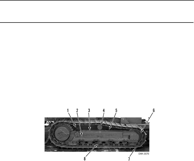
The undercarriage contains the track roller frame (Figure 1, Item 2), track rollers (Figure 1, Item 8), track carrier
roller (Figure 1, Item 4), front idler (Figure 1, Item 6), track adjuster located under cover (Figure 1, Item 5), recoil
spring located under the cover (Figure 1, Item 3), track (Figure 1, Item 7), and pivot shaft (Figure 1, Item 1).
N OT E
The track rollers (Figure 1, Item 8), track carrier roller (Figure 1, Item 4), front idler (Figure
1, Item 6), and pivot shaft (Figure 1, Item 1) use Duo-Cone seal kits. These seal kits
prevent loss of lubricant and keep out dirt and other foreign materials.
Figure 1. Undercarriage Components.
0009