
TM 5-2410-240-23-1
0010
ELECTRO-HYDRAULIC CONTROLS CONTINUED
Brake/Deceleration Pedal Position Sensor
00010
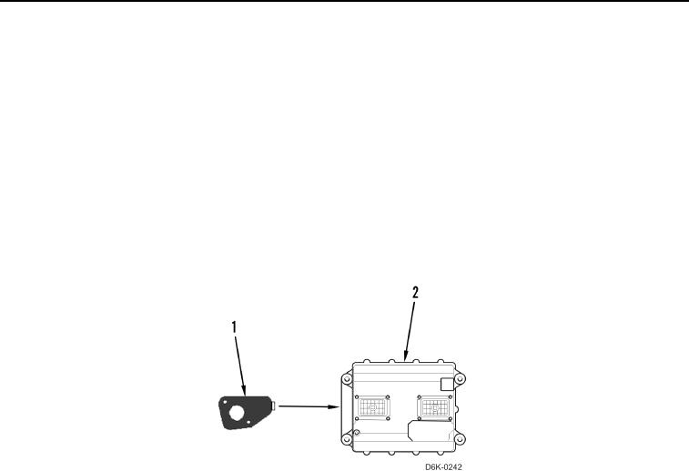
The brake/deceleration pedal position sensor (Figure 2, Item 1) is located in the brake/deceleration pedal housing.
The sensor provides a continuous input to the machine ECM (Figure 2, Item 2). The machine ECM uses this input
to control transmission applied braking and engine deceleration. The engine deceleration parameter is
configurable in the machine ECM for proper machine operation.
The machine ECM (Figure 2, Item 2) provides a 10 Volt supply to the brake/deceleration pedal position sensor
(Figure 2, Item 1). The sensor outputs a pulse width modulated (PWM) signal. The frequency of this signal is
constant at approximately 500Hz. The duty cycle of the signal varies in proportion to the position of the pedal (i.e.,
the duty cycle decreases as the brake/deceleration pedal is depressed).
As the machine ECM (Figure 2, Item 2) interprets a decreased duty cycle, it modifies the signals to the pump and
motor solenoid valves. This allows the drive loops to maintain the maximum hydraulic horsepower for the selected
travel speed while the engine speed decreases.
Figure 2. Brake/Deceleration Pedal Position Sensor.
0010