
TM 5-2410-240-23-1
0010
ELECTRO-HYDRAULIC CONTROLS CONTINUED
Service Brake
00010
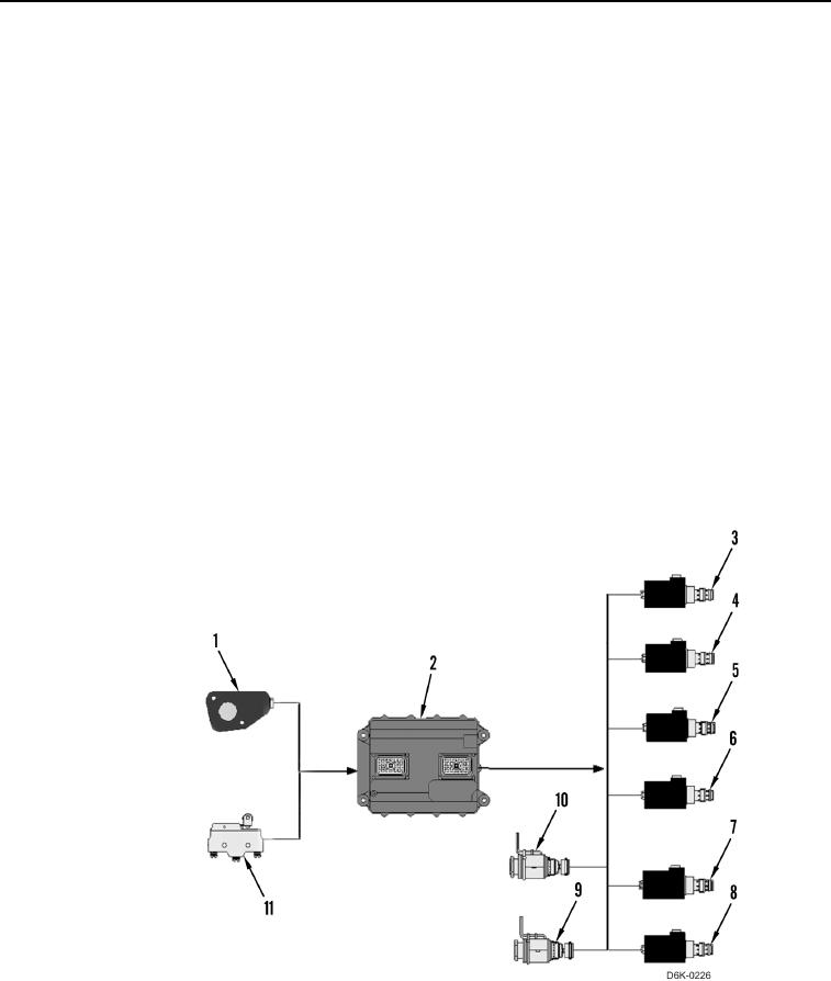
As the operator depresses the brake/deceleration pedal, the duty cycle of the brake/deceleration pedal position
sensor (Figure 3, Item 1) starts to decrease. In turn, the machine ECM (Figure 3, Item 2) starts to decrease the
duty cycles of the motor displacement control solenoid (Figure 3, Item 7) and (Figure 3, Item 8). As the duty cycles
of the solenoids decrease, the hydrostatic drive motors start to upstroke and the machine begins to slow down.
When the hydrostatic drive motors reach the maximum displacements, and the operator continues to depress the
brake/deceleration pedal, the machine ECM (Figure 3, Item 2) starts to decrease the duty cycles of the forward and
reverse solenoids (Figure 3, Items 3, 4, 5, and 6) to shift the proportional solenoid valves in the left and right side
hydrostatic pumps appropriately. As the duty cycles of the solenoids decrease, the left and right side hydrostatic
pumps start to destroke, and the machine continues to slow down until the pumps reach zero angle.
When the operator depresses the brake/deceleration pedal fully (duty cycle between 35% and 31%), the brake/
deceleration pedal limit switch (Figure 3, Item 11) closes, the transmission pilot supply (override) solenoid
(Figure 3, Item 9) de-energizes, and the machine ECM (Figure 3, Item 2) commands the parking brake solenoid
(Figure 3, Item 10) to apply the parking brake. Refer to Parking Brake - Mechanical Operation and to Parking
Brake - Machine ECM Inputs and Outputs and Hydraulic Oil Flow in this work package for information on parking
brake application and release.
N OT E
The parking brake is not normally used to stop the machine and should only be used for
this purpose in case of emergency.
Figure 3. Machine ECM Inputs and Outputs for Service Brake Application.
0010