
TM 5-2410-240-23-1
0017
ECM UNABLE TO COMMUNICATE CONTINUED
00017
6. The following chart provides data link pin information for various ECM J1 connectors.
Table 1. ECM Pin Connectors.
PIN NUMBER
ECM
Data Link (+)
Data Link (-)
Circuit 893 - GN
Circuit 892 - BR
Engine
23
24
Machine
10
20
Messenger
6
5
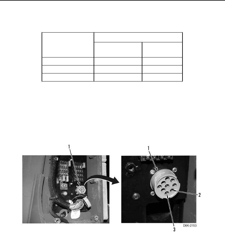
7. At diagnostic connector (Figure 12, Item 1), measure resistance between data link (+) pin D (Figure 12, Item 3)
circuit 893, and data link (-) pin E (Figure 12, Item 2) circuit 892.
If resistance is less than 5.0 Ohms, circuit is OK.Remove jumper wire. Refer to appropriate work package
for ECM replacement instructions. Return to this work package once ECM is replaced. Refer to Initializing
ECM.
If resistance is greater than 5.0 Ohms, there is an op n or a poor connection in data link circuit. Check and
e
repair data link circuit, then try to establish communication with ECM. If ECM still will not communicate,
proceed to appropriate ECM replacement work package. Return to this work package once ECM is
replaced. Refer to Initializing ECM in this work package.
Figure 12. Diagnostic Connector.
0017
END OF TASK
END OF WORK PACKAGE
0017-13/(14 blank)