
TM 5-2410-240-23-1
0017
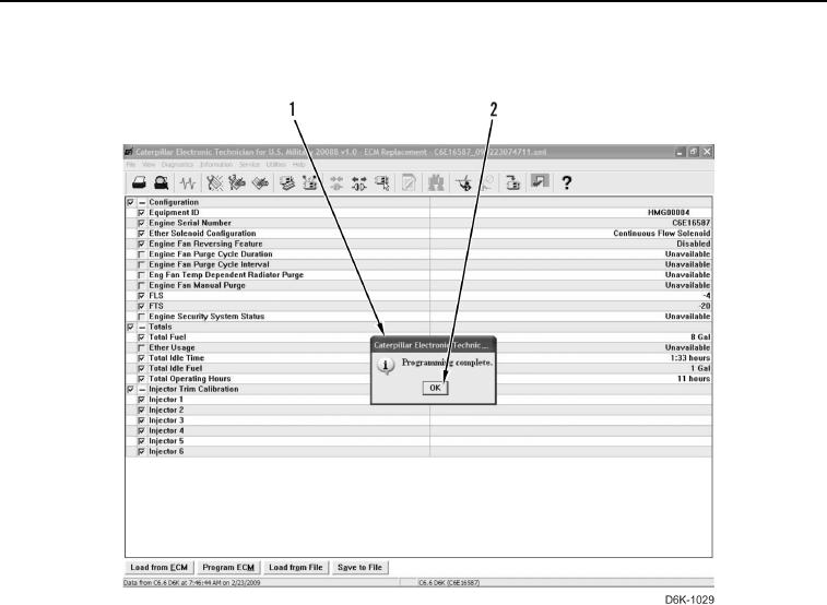
COPY CONFIGURATION TO ECM CONTINUED
7. Select OK button (Figure 7, Item 2) when "Programming complete" dialog box (Figure 7, Item 1) displays.
Figure 7. Programming Complete.
0017
8. The "Programming parameter cannot be programmed..." message may reappear. Select Print button and
select OK button.
9. Start and run engine until operating temperature is reached and verify proper operation of all components
(TM 5-2410-240-10). Check for active diagnostic codes by selecting Active Diagnostic Codes from Diagnostics
menu.
10. Once programming is complete, turn engine start switch to OFF position, shut down Electronic Technician (ET)
on MSD, and disconnect from diagnostic connector.
11. Install diagnostic connector cover.
END OF TASK