
TM 5-2410-240-23-2
0042
REMOVAL CONTINUED
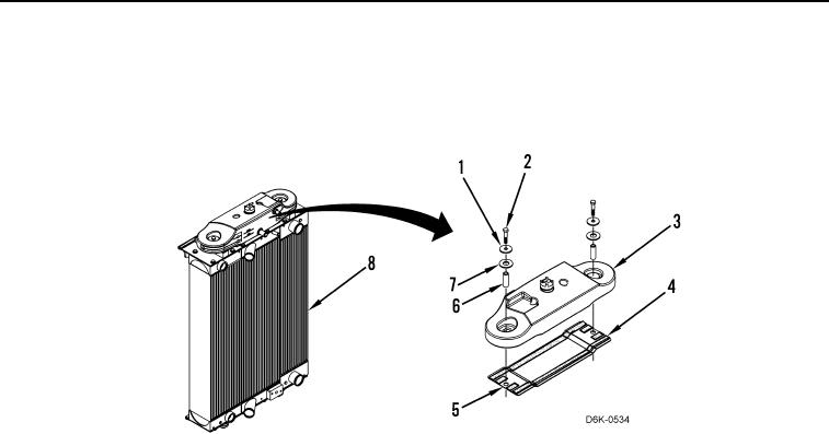
10. Remove two bolts (Figure 4, Item 2), spacers (Figure 4, Item 1), rubber washers (Figure 4, Item 7), spacers
(Figure 4, Item 6), coolant tank (Figure 4, Item 3), gasket (Figure 4, Item 4), and plate (Figure 4, Item 5) from
cooling module (Figure 4, Item 8). Discard gasket.
Figure 4. Coolant Tank and Mounting Hardware.
0042
END OF TASK
CLEANING AND INSPECTION
00042
Clean and inspect all parts IAW Mechanical General Maintenance Instructions (WP 0282).
END OF TASK
INSTALLATION
00042
1. Install plate (Figure 4, Item 5), new gasket (Figure 4, Item 4), coolant tank (Figure 4, Item 3), two spacers
(Figure 4, Item 6), rubber washers (Figure 4, Item 7), spacers (Figure 4, Item 1), and bolts (Figure 4, Item 2) on
cooling module (Figure 4, Item 8).