
TM 5-2410-240-23-2
0042
INSTALLATION CONTINUED
C AU T I O N
Remove caps and plugs from hose ends and open ports before connecting hoses to
coolant tank. Failure to follow this caution may result in damage to equipment.
N OT E
Install hoses as tagged during removal.
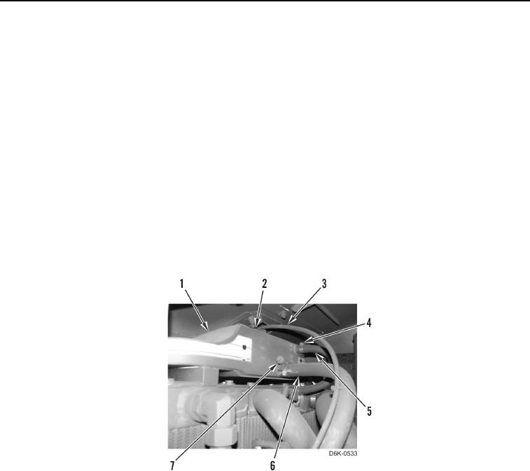
2. Install clamp (Figure 5, Item 7) on hose (Figure 5, Item 6).
3. Connect hose (Figure 5, Item 6) to coolant tank (Figure 5, Item 1).
4. Tighten clamp (Figure 5, Item 7) on hose (Figure 5, Item 6).
5. Install clamp (Figure 5, Item 4) on hose (Figure 5, Item 5).
6. Connect hose (Figure 5, Item 5) to coolant tank (Figure 5, Item 1).
7. Tighten clamp (Figure 5, Item 4) on hose (Figure 5, Item 5).
8. Connect hose (Figure 5, Item 3) to cap (Figure 5, Item 2).
Figure 5. Coolant Tank Hoses.
0042