
TM 5-2410-240-23-2
0069
INSTALLATION
00069
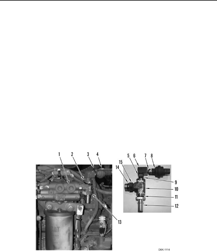
1. Install new O-ring (Figure 4, Item 14) on tee (Figure 4, Item 10).
2. Install tee (Figure 4, Item 10) on filter base (Figure 4, Item 1) and tighten nut (Figure 4, Item 15).
3. Install new O-ring (Figure 4, Item 11) on connector (Figure 4, Item 12).
4. Install connector (Figure 4, Item 12) on tee (Figure 4, Item 10).
5. Install new O-ring (Figure 4, Item 9) on elbow (Figure 4, Item 6).
N OT E
Install elbow as noted during removal.
6. Install elbow (Figure 4, Item 6) on tee (Figure 4, Item 10) and tighten nut (Figure 4, Item 5).
7. Install saddle (Figure 4, Item 13) on tee (Figure 4, Item 10).
8. Install new O-ring (Figure 4, Item 7) on prime pump fuel switch (Figure 4, Item 8).
9. Install prime pump fuel switch (Figure 4, Item 8) on elbow (Figure 4, Item 6).
N OT E
Install electrical connectors as noted during removal.
10. Connect harness (Figure 4, Item 4) on prime pump fuel switch (Figure 4, Item 8).
11. Install new tiedown strap (Figure 4, Item 2) on tee (Figure 4, Item 10) and harness (Figure 4, Item 4).
12. Install new tiedown strap (Figure 4, Item 3) on prime pump fuel switch (Figure 4, Item 8) and harness (Figure 4,
Item 4).
Figure 4. Prime Pump Fuel Switch and Fuel System Hardware.
0069