
TM 5-2410-240-23-2
0106
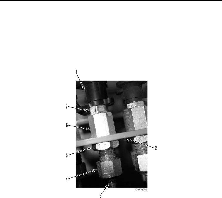
INSTALLATION CONTINUED
6. Install bulkhead fitting (Figure 11, Item 6), test nipple (Figure 11, Item 7), and nut (Figure 11, Item 5) on bracket
(Figure 11, Item 2).
7. Install cap (Figure 11, Item 1) on bulkhead fitting (Figure 11, Item 6).
N OT E
Install hoses as noted at removal.
8. Install hose (Figure 11, Item 3) and tube nut (Figure 11, Item 4) on bulkhead fitting (Figure 11, Item 6).
Figure 11. Hydraulic Diagnostic Connector.
0106