
TM 5-2410-240-23-2
0106
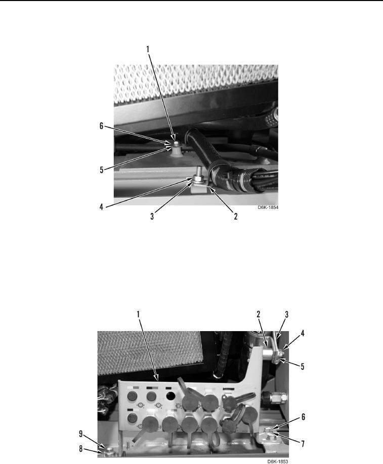
INSTALLATION CONTINUED
15. Install two clips (Figure 14, Items 2 and 5), washers (Figure 14, Items 3 and 6), bolt (Figure 14, Item 1), and nut
(Figure 14, Item 4) on machine.
Figure 14. Diagnostic Hose Harness Attachments.
0106
16. Install bulkhead bracket (Figure 15, Item 1), spacer (Figure 15, Item 8), and bolt (Figure 15, Item 9) on
machine.
17. Install two washers (Figure 15, Item 7) and bolts (Figure 15, Item 6) on bulkhead bracket (Figure 15, Item 1).
18. Install spacer (Figure 15, Item 2), clamp (Figure 15, Item 3), washer (Figure 15, Item 5), and nut (Figure 15,
Item 4) on bulkhead bracket (Figure 15, Item 1).
Figure 15. Hydraulic Diagnostic Center.
0106
END OF TASK