
TM 5-2410-240-23-2
0107
CLEANING AND INSPECTION
000107
Clean and inspect all components IAW Mechanical General Maintenance Instructions (WP 0282).
END OF TASK
INSTALLATION
000107
N OT E
Install hoses, new tiedown straps, and clamps as noted during removal.
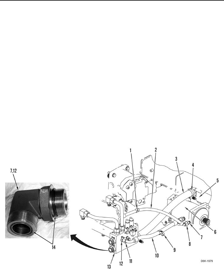
1. Install two clamps (Figure 3, Item 4) on hose (Figure 3, Item 3).
2. Install hose (Figure 3, Item 3) on hydraulic tank (Figure 3, Item 5) and manifold (Figure 3, Item 13). Tighten two
clamps (Figure 3, Item 4).
3. Install two new O-rings (Figure 3, Item 14) on each fitting (Figure 3, Item 12).
4. Install two fittings (Figure 3, Item 12), hose (Figure 3, Item 10) and two tube nuts (Figure 3, Item 11) on
manifold (Figure 3, Item 13) and motor (Figure 3, Item 6).
5. Install two new O-rings (Figure 3, Item 14) on each fitting (Figure 3, Item 7).
6. Install two fittings (Figure 3, Item 7), hose (Figure 3, Item 2) and two tube nuts (Figure 3, Item 8) on manifold
(Figure 3, Item 13) and motor (Figure 3, Item 6).
7. Install new dual tiedown strap (Figure 3, Item 1) on hose (Figure 3, Item 2).
8. Install new dual tiedown strap (Figure 3, Item 9) on hose (Figure 3, Item 10).
Figure 3. Supply Hose.
0107