
TM 5-2410-240-23-2
0108
REMOVAL CONTINUED
N OT E
Mark position and routing of hoses and lines to aid installation.
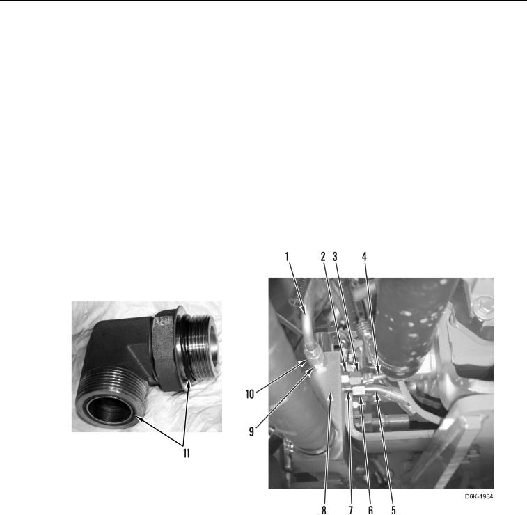
11. Loosen tube nut (Figure 2, Item 10) and remove line (Figure 2, Item 1) from fitting (Figure 2, Item 9). Remove
line from machine.
12. Remove fitting (Figure 2, Item 9) from manifold (Figure 2, Item 8).
13. Remove two O-rings (Figure 2, Item 11) from fitting (Figure 2, Item 9). Discard O-rings.
14. Loosen tube nut (Figure 2, Item 3) and remove line (Figure 2, Item 4) from fitting (Figure 2, Item 2).
15. Remove fitting (Figure 2, Item 2) from manifold (Figure 2, Item 8).
16. Remove two O-rings (Figure 2, Item 11) from fitting (Figure 2, Item 2). Discard O-rings.
17. Loosen tube nut (Figure 2, Item 6) and remove line (Figure 2, Item 5) from fitting (Figure 2, Item 7).
18. Remove fitting (Figure 2, Item 7) from manifold (Figure 2, Item 8).
19. Remove two O-rings (Figure 2, Item 11) from fitting (Figure 2, Item 7). Discard O-rings.
Figure 2. Right Motor Hose to Manifold.
0108
N OT E
Mark position and routing of hoses and lines to aid installation.
20. Loosen tube nut (Figure 3, Item 3) and remove hose (Figure 3, Item 4) from fitting (Figure 3, Item 2).
21. Remove dual tiedown strap (Figure 3, Item 5) and hose (Figure 3, Item 4) from machine. Discard tiedown
strap.
22. Remove fitting (Figure 3, Item 2) from pump (Figure 3, Item 1).
23. Remove two O-rings (Figure 3, Item 17) from fitting (Figure 3, Item 2). Discard O-rings.
24. Remove two dual tiedown straps (Figure 3, Item 5) from hose (Figure 3, Item 4). Discard tiedown straps.