
TM 5-2410-240-23-2
0107
INSTALLATION CONTINUED
N OT E
Install hoses, new tiedown straps, and clamps as noted during removal.
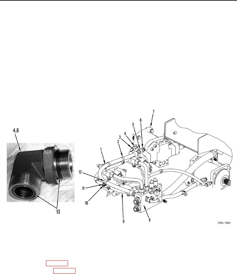
9. Install two new O-rings (Figure 4, Item 13) on each fitting (Figure 4, Item 4).
10. Install two fittings (Figure 4, Item 4), hose (Figure 4, Item 9), and two tube nuts (Figure 4, Item 3) on motor
(Figure 4, Item 7) and manifold (Figure 4, Item 8).
11. Install two new O-rings (Figure 4, Item 13) on each fitting (Figure 4, Item 6).
12. Install two fittings (Figure 4, Item 6), hose (Figure 4, Item 1), and two tube nuts (Figure 4, Item 5) on motor
(Figure 4, Item 7) and manifold (Figure 4, Item 8).
13. Install two clamps (Figure 4, Item 12), washer (Figure 4, Item 10), and nut (Figure 4, Item 11) on hoses
(Figure 4, Items 1 and 9).
14. Install two new dual tiedown straps (Figure 4, Item 2) on hose (Figure 4, Item 1) and hose (Figure 4, Item 9).
Figure 4. Motor Drain Hose.
0107
END OF TASK
FOLLOW-ON TASKS
000107
1. Fill hydraulic fluid (WP 0160).
2. Install bottom guards (WP 0156).
3. Verify correct operation of machine (TM 5-2410-240-10).
END OF TASK
END OF WORK PACKAGE
0107-5/(6 blank)