
TM 5-2410-240-23-2
0108
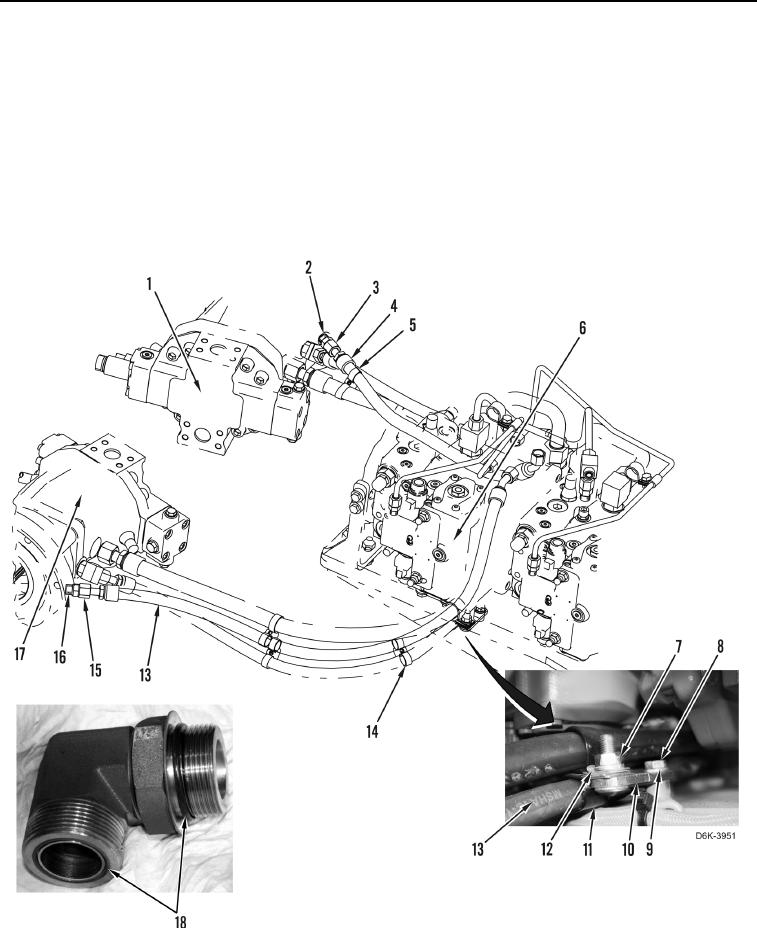
REMOVAL CONTINUED
25. Remove nut (Figure 3, Item 7), washer (Figure 3, Item 12) and two clamps (Figure 3, Item 11) from bracket
(Figure 3, Item 10) and hose (Figure 3, Item 13).
26. Remove bolt (Figure 3, Item 8), washer (Figure 3, Item 9) and bracket (Figure 3, Item 10) from machine.
27. Loosen tube nut (Figure 3, Item 15) and remove hose (Figure 3, Item 13) from fitting (Figure 3, Item 17).
28. Remove O-ring (Figure 3, Item 18) from fitting (Figure 3, Item 17). Discard O-ring.
29. Pull hose (Figure 3, Item 13) out from under pump (Figure 3, Item 6). Remove hose from machine.
30. Remove fitting (Figure 3, Item 16) from pump (Figure 3, Item 17).
31. Remove two O-rings (Figure 3, Item 18) from fitting (Figure 3, Item 16). Discard O-rings.
Figure 3. Pump Hoses.
0108