
TM 5-2410-240-23-2
0108
REMOVAL CONTINUED
N OT E
Mark position and routing of hoses to aid installation.
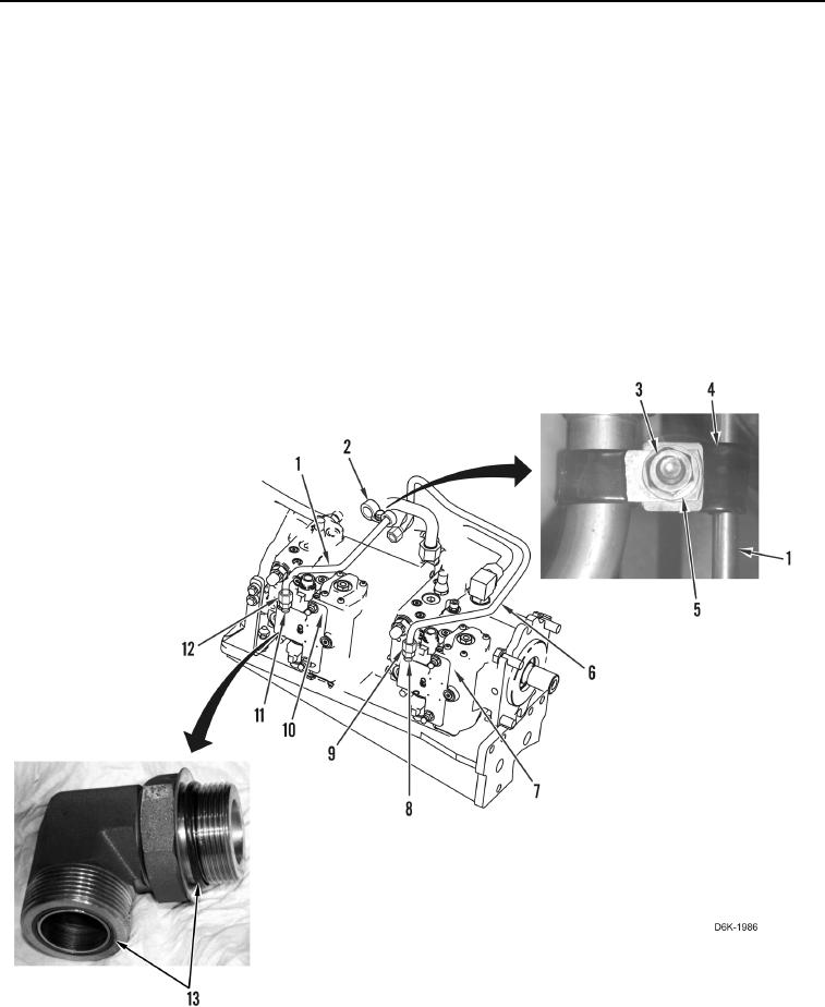
32. Remove nut (Figure 4, Item 3), two washers (Figure 4, Item 5), bolt (Figure 4, Item 2) and clamp (Figure 4,
Item 4) from line (Figure 4, Item 1).
33. Loosen tube nut (Figure 4, Item 12) and remove line (Figure 4, Item 1) from fitting (Figure 4, Item 11). Remove
line from machine.
34. Remove fitting (Figure 4, Item 11) from pump (Figure 4, Item 10).
35. Remove two O-rings (Figure 4, Item 13) from fitting (Figure 4, Item 11).
36. Loosen tube nut (Figure 4, Item 9) and remove line (Figure 4, Item 6) from fitting (Figure 4, Item 8).
37. Remove fitting (Figure 4, Item 8) from pump (Figure 4, Item 7).
38. Remove two O-rings (Figure 4, Item 13) from fitting (Figure 4, Item 8).
Figure 4. Pump Hoses.
0108
END OF TASK