
TM 5-2410-240-23-2
0108
INSTALLATION CONTINUED
N OT E
Install hoses and lines as noted during removal.
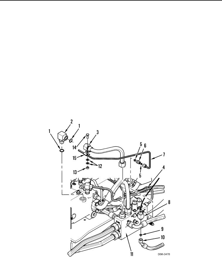
28. Install new O-ring (Figure 7, Item 9) on fitting (Figure 7, Item 8).
29. Install hose (Figure 7, Item 10) on fitting (Figure 7, Item 8).
30. Install two new O-rings (Figure 7, Item 5) on fitting (Figure 7, Item 6).
31. Install fitting (Figure 7, Item 6) on manifold (Figure 7, Item 11).
32. Install line (Figure 7, Item 7) on fitting (Figure 7, Item 6).
33. Install new dual tiedown strap (Figure 7, Item 4) on line (Figure 7, Item 3).
34. Install two new O-rings (Figure 7, Item 1) on fitting (Figure 7, Item 2).
35. Install fitting (Figure 7, Item 2) on pump.
36. Install line (Figure 7, Item 3) on fitting (Figure 7, Item 2).
37. Install clamp (Figure 7, Item 15), bolt (Figure 7, Item 14), two washers (Figure 7, Item 12) and nut (Figure 7,
Item 13) on line (Figure 7, Item 7).
Figure 7. Left Motor Hose to Manifold.
0108
END OF TASK