
TM 5-2410-240-23-2
0150
REMOVAL CONTINUED
N OT E
Note location of tiedown straps and tag and mark electrical connectors to aid installation.
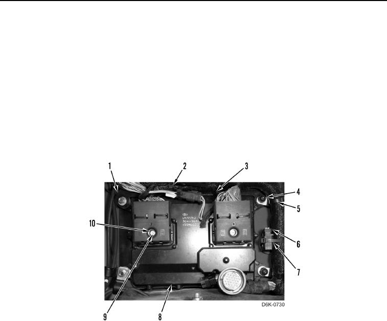
12. Loosen two screws (Figure 7, Item 9) and disconnect harness connectors (Figure 7, Item 10) from machine
ECM (Figure 7, Item 8).
13. Remove tiedown strap (Figure 7, Item 7) and connector cap (Figure 7, Item 6) from harness (Figure 7, Item 3).
Discard tiedown strap.
14. Remove three tiedown straps (Figure 7, Item 2) from harness (Figure 7, Item 3) and from bracket (Figure 7,
Item 1). Discard tiedown straps.
15. Remove two tiedown straps (Figure 7, Item 5) from harness (Figure 7, Item 3) and from clips (Figure 7, Item 4).
Discard tiedown straps.
Figure 7. Machine ECM Harness Connectors, Connector Cap, and Harness Retaining Hardware.
0150