
TM 5-2410-240-23-2
0154
REMOVAL CONTINUED
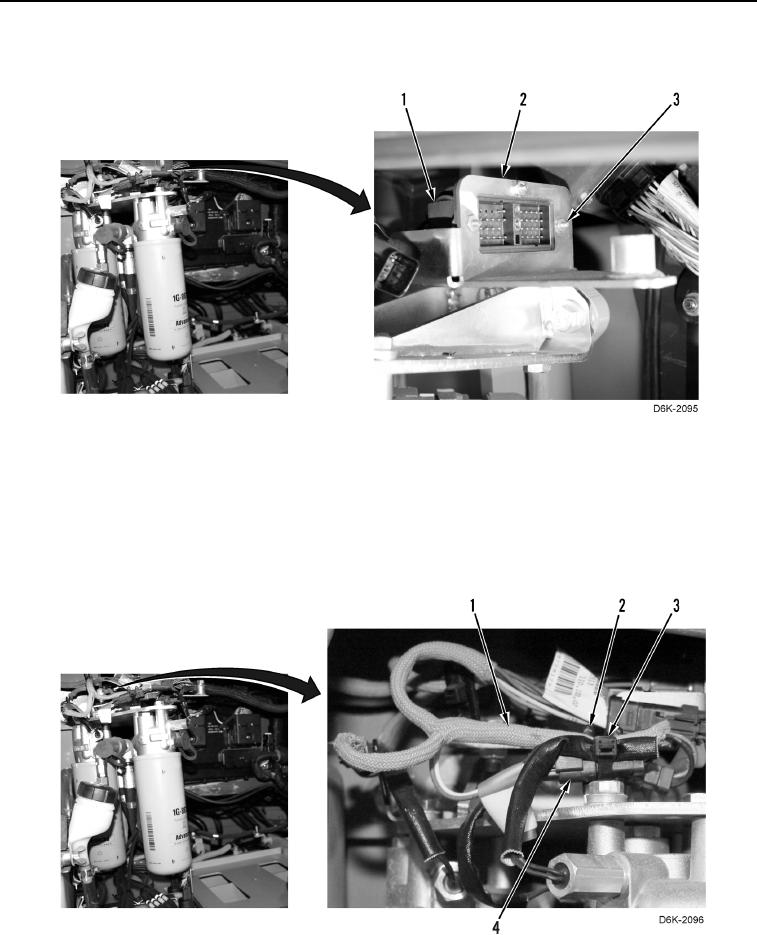
6. Remove three screws (Figure 3, Item 3) and chassis harness (Figure 3, Item 1) from bracket (Figure 3, Item 2).
Figure 3. Chassis Harness and Retaining Hardware Above Hydraulic Oil Filters.
0154
N OT E
Note location of tiedown straps and tag and mark electrical connectors to aid installation.
7. Remove three tiedown straps (Figure 4, Item 3) from chassis harness (Figure 4, Item 1) and from clips
(Figure 4, Item 2). Discard tiedown straps.
8. Disconnect chassis harness (Figure 4, Item 1) from three oil filter bypass switches (Figure 4, Item 4).
Figure 4. Oil Filter Bypass Switches, Chassis Harness, and
Retaining Hardware Above Hydraulic Oil Filters.
0154