• Home
  • Download PDF
  • Order CD-ROM
  • Order in Print
Figure 6. Chassis Harness Ground Connector Behind Hydraulic Oil Filter Base.
Figure 8. Harness Retaining Hardware Inside Frame.

Field Maintenance Manual 2 D6K Dozer Type I With Winch and Type II With Ripper
Page Navigation
  1021    1022    1023    1024    1025  1026  1027    1028    1029    1030    1031  
img
.
TM 5-2410-240-23-2
0154
REMOVAL CONTINUED
N OT E
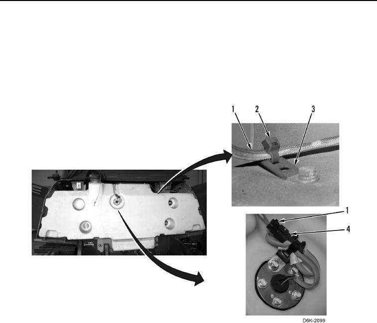
Note location of tiedown straps and tag and mark electrical connectors to aid installation.
12. Disconnect chassis harness (Figure 7, Item 1) from fuel level sensor (Figure 7, Item 4).
13. Remove four tiedown straps (Figure 7, Item 2) from chassis harness (Figure 7, Item 1) and clips
(Figure 7, Item 3). Discard tiedown straps.
Figure 7. Fuel Level Sensor, Chassis Harness, and Retaining Hardware on Fuel Tank.
0154
0154-7


Privacy Statement
Press Release
Contact

© Copyright Integrated Publishing, Inc.. All Rights Reserved.