
TM 5-2410-240-23-3
0174
INSTALLATION CONTINUED
N OT E
Remove all caps from hose ends and fuel lines before installation.
Install all hoses as noted during removal.
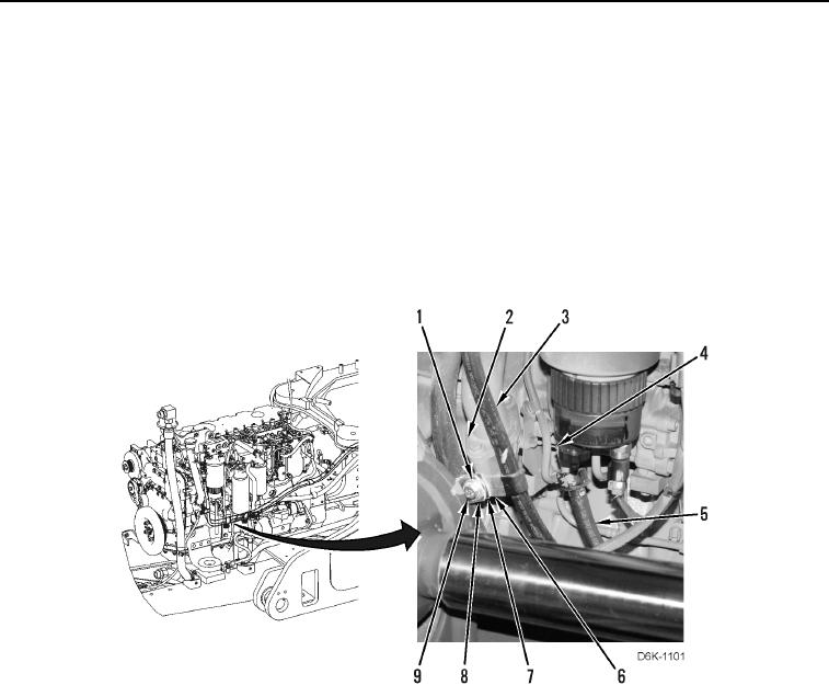
9. Install fuel hose (Figure 26, Item 5) on machine.
10. Connect fuel hose (Figure 26, Item 5) to fuel line (Figure 26, Item 4).
11. Install inner clamp (Figure 26, Item 6) on fuel hose (Figure 26, Item 3).
12. Install inner clamp (Figure 26, Item 6), middle clamp (Figure 26, Item 7), outer clamp (Figure 26, Item 8),
washer (Figure 26, Item 1), and bolt (Figure 26, Item 9) on engine (Figure 26, Item 2).
Figure 26. Fuel Hose Connector and Retaining Hardware Near Front of Engine.
0174