
TM 5-2410-240-23-3
0174
INSTALLATION CONTINUED
N OT E
Remove all caps and plugs from hose ends, fittings, and ports in fuel tank before
installation.
Install all hoses and fittings as noted during removal.
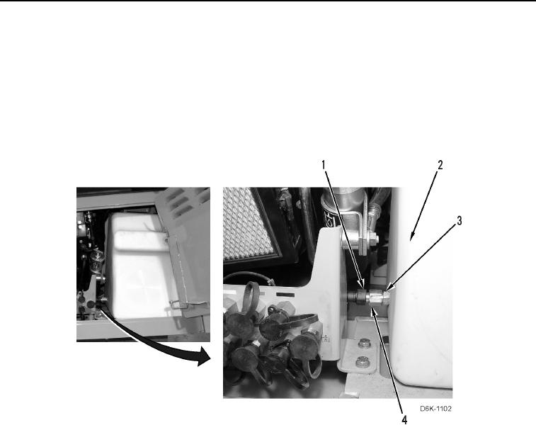
33. Install check valve (Figure 37, Item 3) and connector (Figure 37, Item 4) on fuel tank (Figure 37, Item 2).
34. Connect fuel hose (Figure 37, Item 1) to connector (Figure 37, Item 4).
Figure 37. Fuel Hose, Connector, and Check Valve Behind Left Rear Access Door.
0174
35. Close left rear access door (TM 5-2410-240-10).