
TM 5-2410-240-23-3
0174
INSTALLATION CONTINUED
N OT E
Remove all caps and plugs from hose ends fittings, and ports in fuel tank before
,
installation.
Install all hoses and fittings as noted during removal.
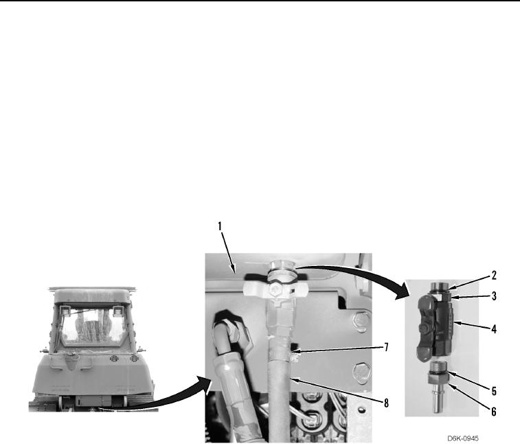
40. Install new O-ring (Figure 39, Item 2) on drain valve (Figure 39, Item 4).
41. Install drain valve (Figure 39, Item 4) on fuel tank (Figure 39, Item 1) and tighten nut (Figure 39, Item 3).
42. Install new O-ring (Figure 39, Item 5) on connector (Figure 39, Item 6).
43. Install connector (Figure 39, Item 6) on drain valve (Figure 39, Item 4).
44. Install drain hose (Figure 39, Item 7) on connector (Figure 39, Item 6).
45. Install clamp (Figure 39, Item 8) on drain hose (Figure 39, Item 7).
Figure 39. Fuel Tank Drain Hardware on Rear of Machine.
0174