
TM 5-2410-240-23-3
0174
INSTALLATION CONTINUED
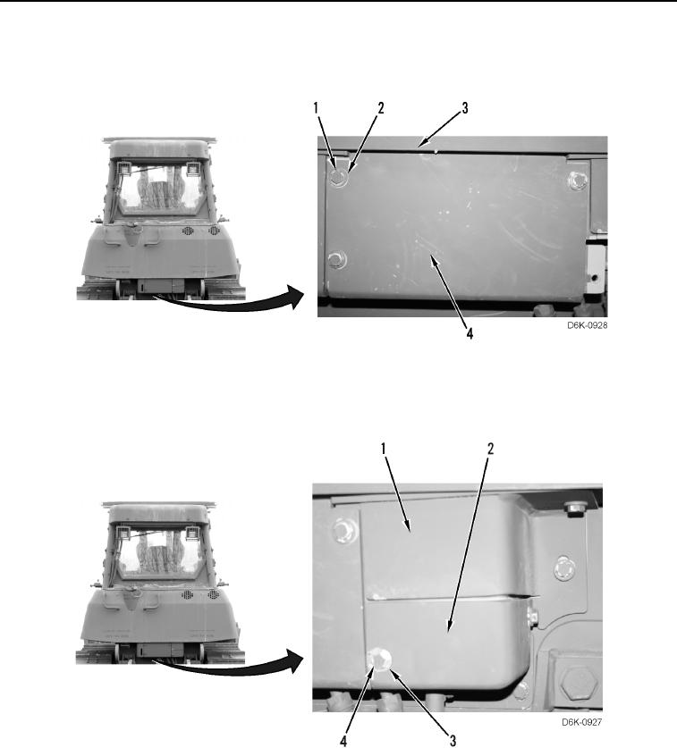
46. Install center access cover (Figure 40, Item 4), three washers (Figure 40, Item 2), and bolts (Figure 40, Item 1)
on machine (Figure 40, Item 3).
Figure 40. Center Access Cover and Retaining Hardware on Rear of Machine.
0174
47. Install lower access cover (Figure 41, Item 2), two washers (Figure 41, Item 3), and bolts (Figure 41, Item 4) on
upper access cover (Figure 41, Item 1).
Figure 41. Lower Access Cover and Retaining Hardware on Rear of Machine.
0174