
TM 5-2410-240-23-3
0176
REMOVAL CONTINUED
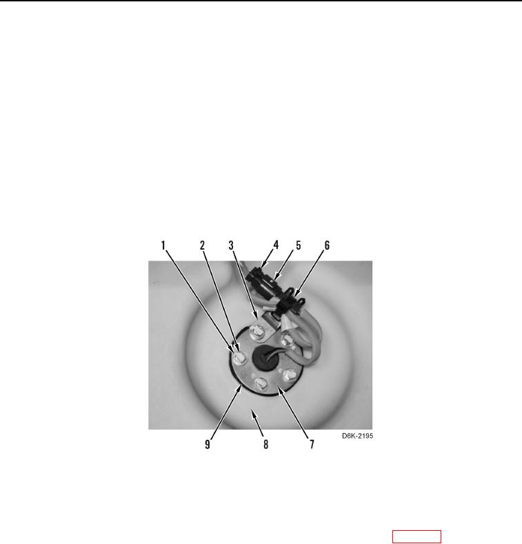
9. Disconnect chassis harness connector (Figure 4, Item 4) from fuel level sender harness (Figure 4, Item 5) and
remove tiedown strap (Figure 4, Item 6) from harness (Figure 4, Item 5) and clip (Figure 4, Item 3). Discard
tiedown strap.
C AU T I O N
Fuel level sender has a long wire arm and float inside fuel tank. Do not bend wire arm or
damage float when removing fuel level sender from fuel tank.
N OT E
Plug all ports in fuel tank.
Note position of sender and bolts to aid installation.
10. Remove five bolts (Figure 4, Item 2), washers (Figure 4, Item 1), clip (Figure 4, Item 3), fuel level sender
(Figure 4, Item 7), and gasket (Figure 4, Item 9) from fuel tank (Figure 4, Item 8). Discard gasket.
Figure 4. Fuel Level Sender and Retaining Hardware.
0176
END OF TASK
CLEANING AND INSPECTION
000176
Clean and inspect all components IAW Mechanical General Maintenance Instructions (WP 0282).
END OF TASK