
TM 5-2410-240-23-3
0177
REMOVAL CONTINUED
N OT E
Hose clamps are all removed using the same general method. This procedure covers
removal of one hose clamp from machine.
Note routing of hoses to aid installation.
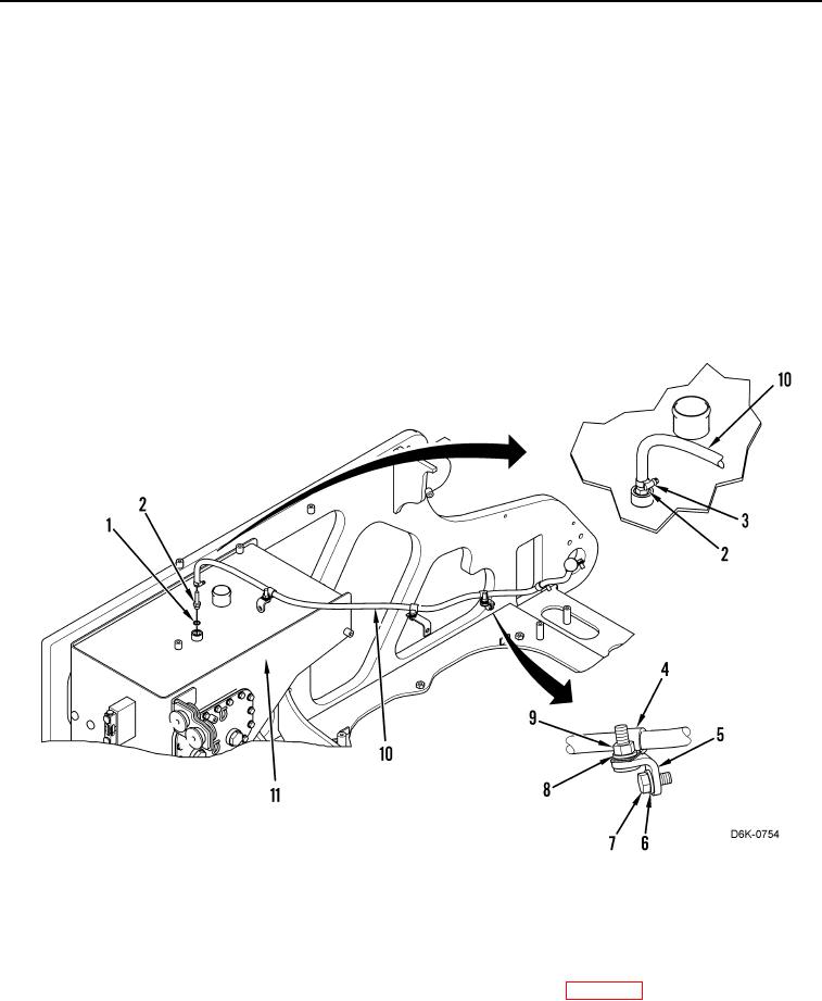
6. Loosen clamp (Figure 2, Item 3) and disconnect hose (Figure 2, Item 10) from connector (Figure 2, Item 2).
7. Remove O-ring (Figure 2, Item 1) and connector (Figure 2, Item 2) from hydraulic tank (Figure 2, Item 11).
Discard O-ring.
8. Remove nut (Figure 2, Item 9), washer (Figure 2, Item 8), and clip (Figure 2, Item 4) from machine. Position
hose (Figure 2, Item 10) aside.
9. Remove bolt (Figure 2, Item 7), washer (Figure 2, Item 6), and bracket (Figure 2, Item 5) from machine.
10. Remove hose (Figure 2, Item 10) from machine.
Figure 2. Hydraulic Tank Vent Hose.
0177
END OF TASK
CLEANING AND INSPECTION
000177
Clean and inspect all parts IAW Mechanical General Maintenance Instructions (WP 0282).
END OF TASK