
TM 5-2410-240-23-3
0176
INSTALLATION
000176
C AU T I O N
Fuel level sender has a long wire arm and float inside fuel tank. Do not bend wire arm or
damage float when installing fuel level sender from fuel tank.
N OT E
Remove plug from port in fuel tank before installing fuel level sender.
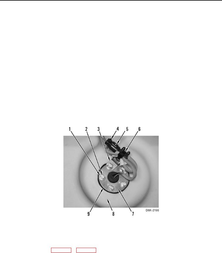
1. Install new gasket (Figure 5, Item 9) and fuel level sender (Figure 5, Item 7) on fuel tank (Figure 5, Item 8).
N OT E
Install gasket and sender as noted during removal. Bolt holes for sender and gasket will
allow for installation in only one position.
2. Install clip (Figure 5, Item 3), five washers (Figure 5, Item 1), and bolts (Figure 5, Item 2) on fuel level sender
(Figure 5, Item 7).
3. Connect chassis harness connector (Figure 5, Item 4) to fuel level sender harness (Figure 5, Item 5) and install
new tiedown strap (Figure 5, Item 6) on harness (Figure 5, Item 5) and clip (Figure 5, Item 3).
Figure 5. Fuel Level Sender and Retaining Hardware.
0176
END OF TASK
FOLLOW-ON TASKS
000176
2. Refuel machine (TM 5-2410-240-10).
3. Verify correct operation of machine (TM 5-2410-240-10).
END OF TASK
END OF WORK PACKAGE