
TM 5-2410-240-23-3
0177
INSTALLATION
000177
N OT E
Hose clamps are all installed using the same general method. This procedure covers
installation of one hose clamp on machine.
Install hoses as noted during removal.
1. Install bracket (Figure 2, Item 5), washer (Figure 2, Item 6), and bolt (Figure 2, Item 7) on machine.
2. Remove caps and position hose (Figure 2, Item 10) on machine and install clip (Figure 2, Item 4), washer
(Figure 2, Item 8), and nut (Figure 2, Item 9) on machine.
3. Install new O-ring (Figure 2, Item 1) and connector (Figure 2, Item 2) on hydraulic tank (Figure 2, Item 11).
4. Connect hose (Figure 2, Item 10) to connector (Figure 2, Item 2) and tighten clamp (Figure 2, Item 3).
N OT E
Install hoses as noted during removal.
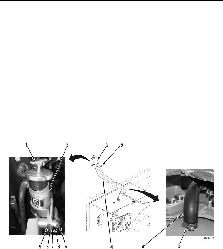
5. Remove caps, install hose (Figure 3, Item 4) on machine, and tighten clamp (Figure 3, Item 3).
6. Install fill tube (Figure 3, Item 2) on hose (Figure 3, Item 4) and tighten clamp (Figure 3, Item 5).
7. Install spacer (Figure 3, Item 9), clamp (Figure 3, Item 8), washer (Figure 3, Item 7), and nut (Figure 3, Item 6)
on machine.
8. Install fill tube cap (Figure 3, Item 1) on fill tube (Figure 3, Item 2).
Figure 3. Hydraulic Tank Fill Hose.
0177