
TM 5-2410-240-23-3
0181
ASSEMBLY
000181
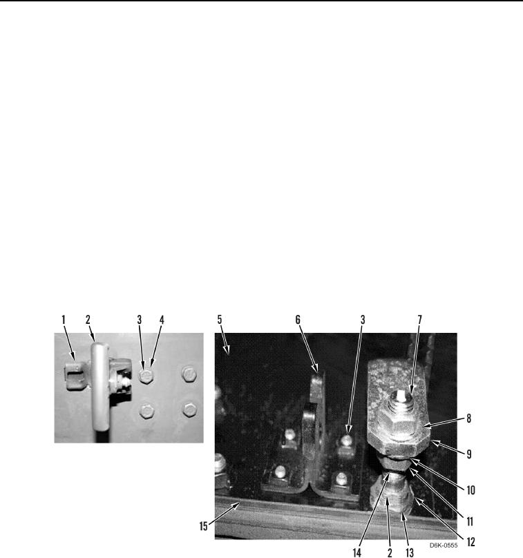
1. Install two brackets (Figure 7, Item 1) and latches (Figure 7, Item 2) on radiator access door (Figure 7, Item 5).
2. Install two washers (Figure 7, Item 12) and nuts (Figure 7, Item 13) on latches (Figure 7, Item 2).
3. Tighten two nuts (Figure 7, Item 13) on latches (Figure 7, Item 2).
4. Bend tabs on washers (Figure 7, Item 12) upward and against nuts (Figure 7, Item 13).
N OT E
Maintain latch adjustment as noted during removal.
5. Install two nuts (Figure 7, Item 11) on latches (Figure 7, Item 2) so thread counts (Figure 7, Item 14) are as
noted during removal.
6. Install two washers (Figure 7, Item 10) on latches (Figure 7, Item 2).
7. Position handles on latches (Figure 7, Item 2) as shown.
8. Install two pawls (Figure 7, Item 9) on latches (Figure 7, Item 2) as shown.
9. Install two washers (Figure 7, Item 8) and nuts (Figure 7, Item 7) on latches (Figure 7, Item 2).
10. Install two brackets (Figure 7, Item 6), eight washers (Figure 7, Item 4), and bolts (Figure 7, Item 3) on radiator
access door (Figure 7, Item 5).
11. Install seal (Figure 7, Item 15) on radiator access door (Figure 7, Item 5).
Figure 7. Radiator Access Door Hardware.
0181