
TM 5-2410-240-23-3
0212
RIGHT SIDE CONSOLE REMOVAL CONTINUED
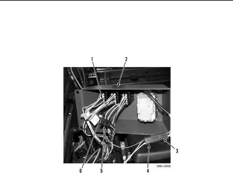
5. Disconnect three winch control harness connectors (Figure 9, Item 1) from control panel (Figure 9, Item 2).
6. Disconnect ripper control harness connector (Figure 9, Item 3) from main harness connector (Figure 9,
Item 4).
7. Disconnect 12V harness connector (Figure 9, Item 5) from 12V accessory receptacle (Figure 9, Item 6).
8. Remove 12V accessory receptacle (Figure 9, Item 6) from control panel (Figure 9, Item 2).
Figure 9. Control Panel Electrical Connectors - Rear.
0212