
TM 5-2410-240-23-3
0212
LEFT SIDE CONSOLE REMOVAL CONTINUED
4. Open left rear access door (TM 5-2410-240-10).
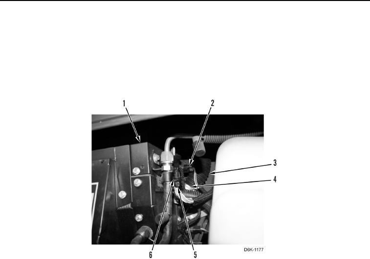
5. Disconnect electrical connector (Figure 5, Item 2) from heater and air conditioning unit (Figure 5, Item 1).
6. Disconnect electrical connector (Figure 5, Item 6) from main harness connector (Figure 5, Item 5).
7. Remove clamp (Figure 5, Item 4) and hose (Figure 5, Item 3) from heater and air conditioning unit (Figure 5,
Item 1). Remove clamp (Figure 5, Item 4) from hose (Figure 5, Item 3).
8. Remove left side console from cab.
Figure 5. Heater, A/C Duct Hose.
0212
END OF TASK