• Home
  • Download PDF
  • Order CD-ROM
  • Order in Print
Figure 5. Heater, A/C Duct Hose.
Figure 8. Control Panel Electrical Connectors - Front.

Field Maintenance Manual 3 D6K Dozer Type I With Winch and Type II With Ripper
Page Navigation
  358    359    360    361    362  363  364    365    366    367    368  
img
.
TM 5-2410-240-23-3
0212
RIGHT SIDE CONSOLE REMOVAL
000212
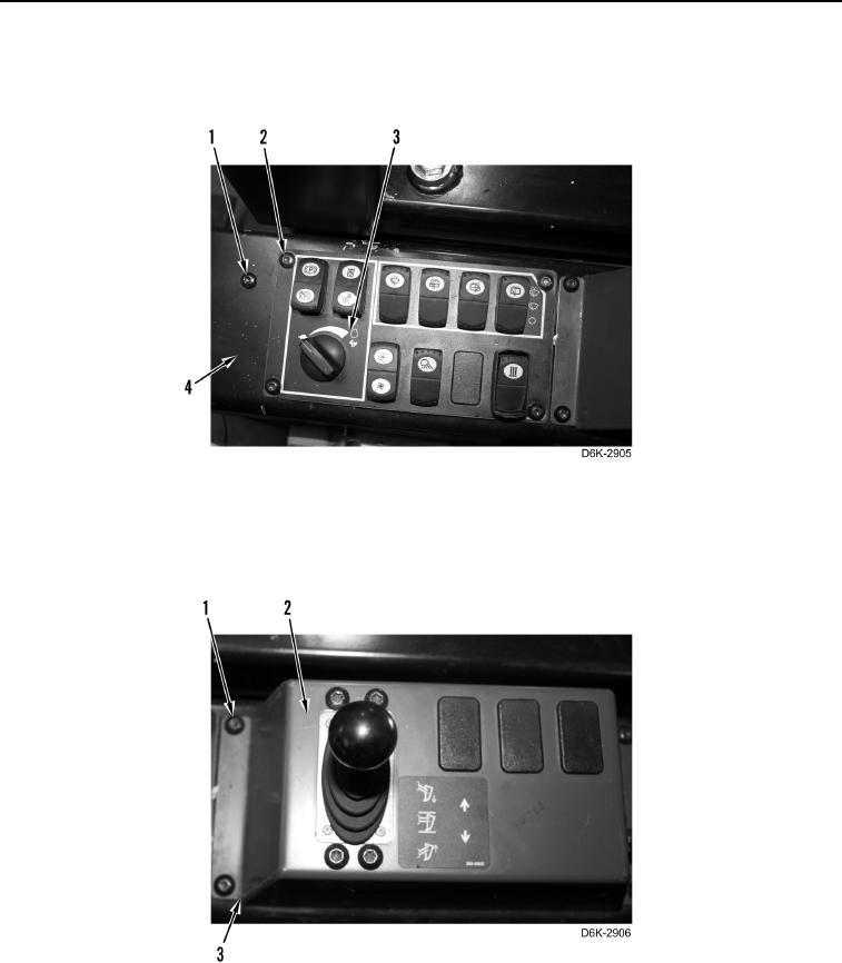
1. Remove three screws (Figure 6, Item 1), four screws (Figure 6, Item 2), and front control panel (Figure 6,
Item 3) from right side console (Figure 6, Item 4).
Figure 6. Control Panel - Front.
0212
2. Remove four screws (Figure 7, Item 1) and rear control panel (Figure 7, Item 2) from right side console
(Figure 7, Item 3).
Figure 7. Control Panel - Rear.
0212
0212-6


Privacy Statement
Press Release
Contact

© Copyright Integrated Publishing, Inc.. All Rights Reserved.